|
|
|
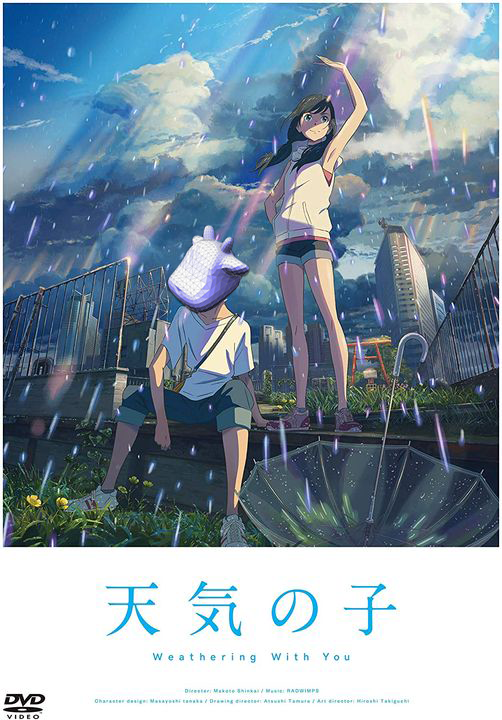
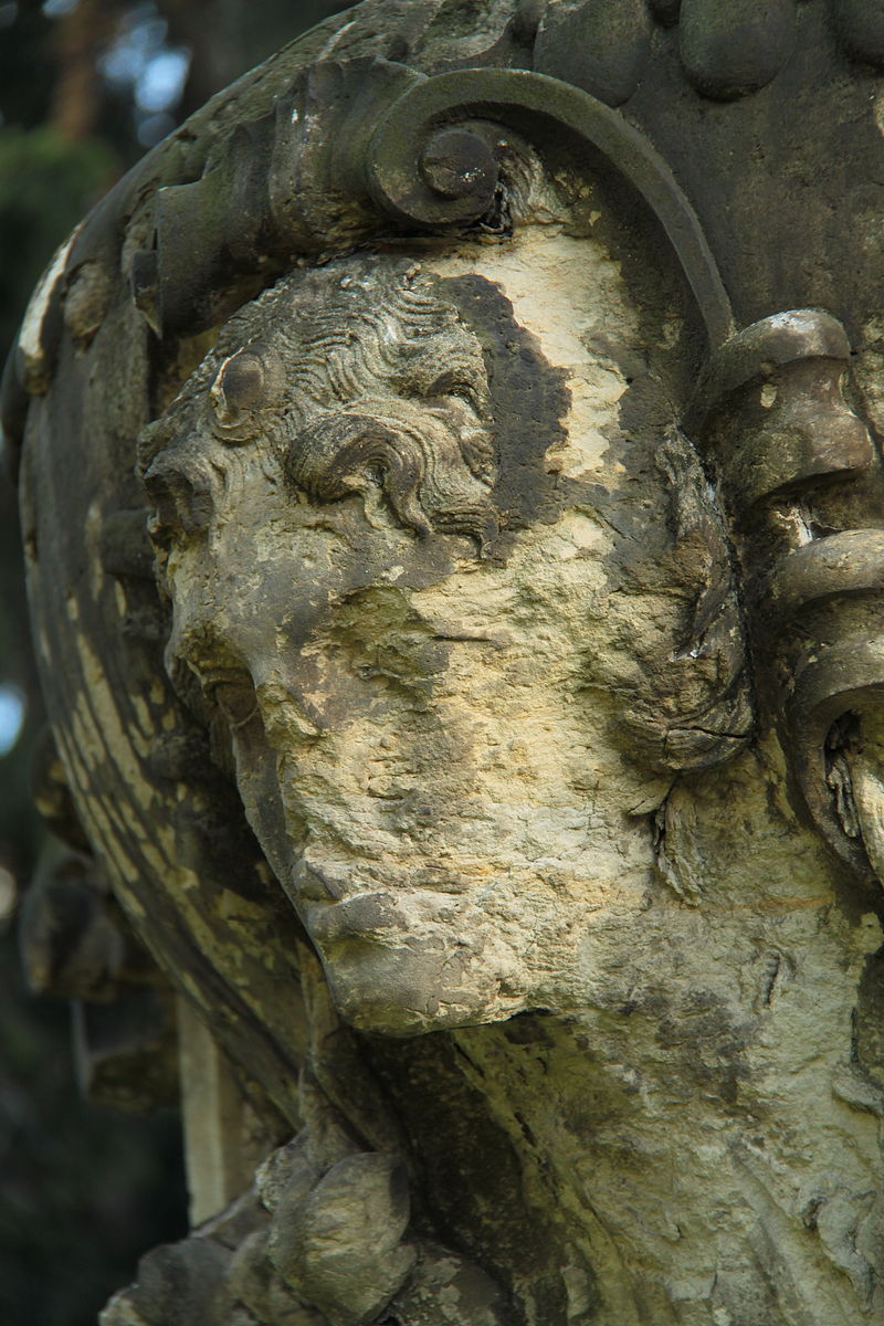
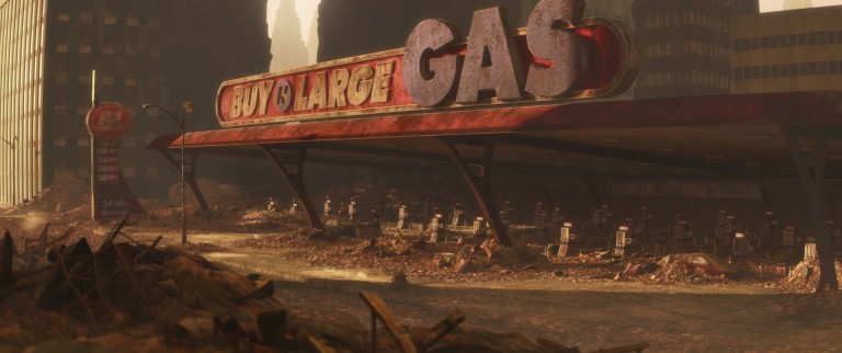
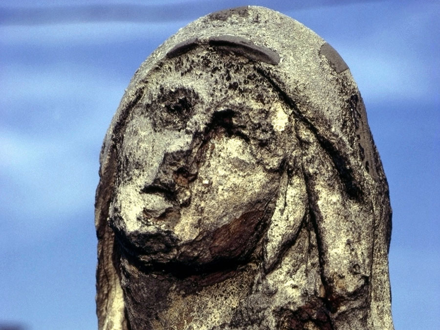
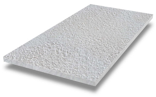
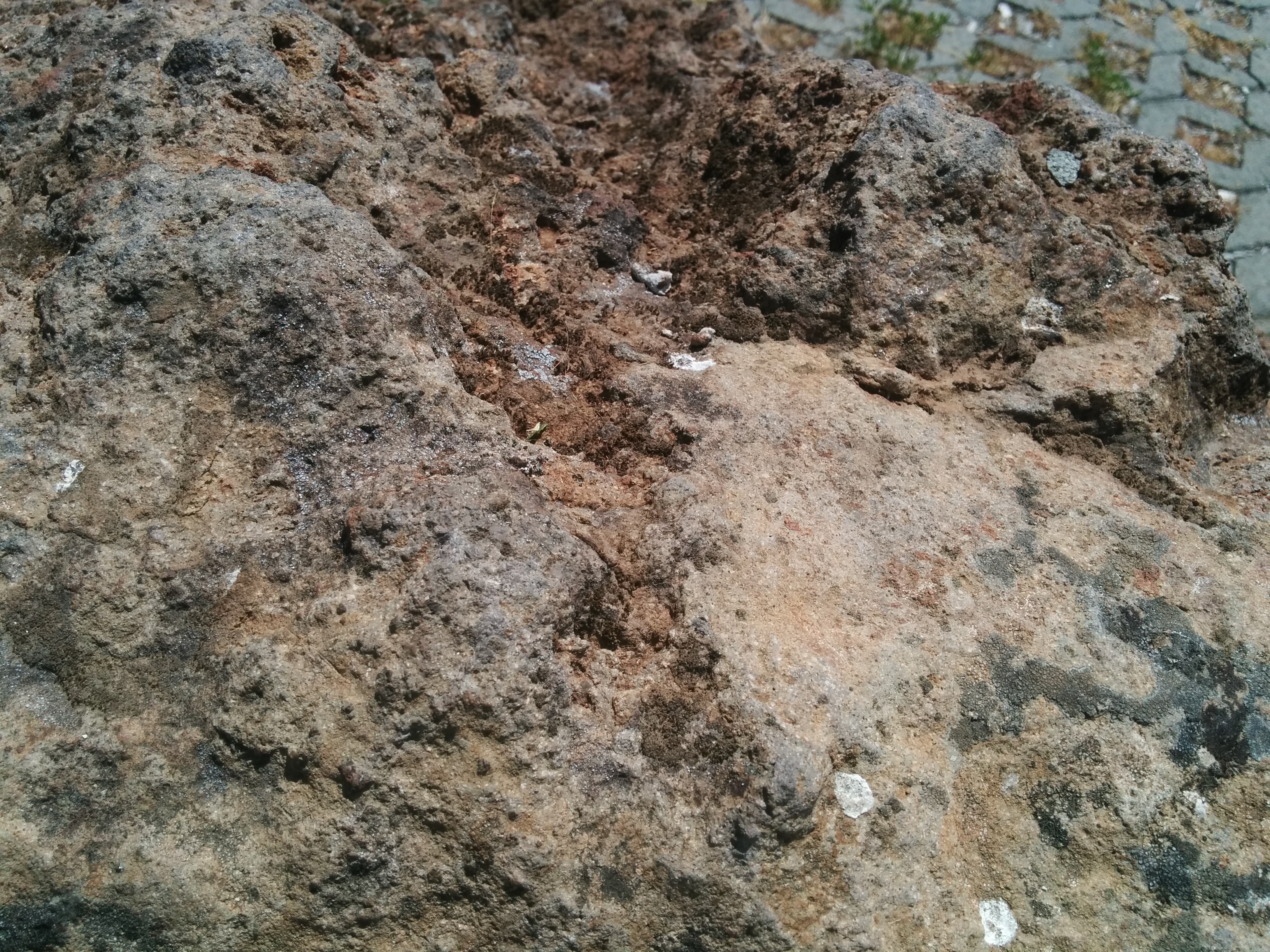
Weathered buildings and statues have complex geometric shapes that pose a significant challenge for 3D-animators and artists seeking to render realistic scenes (Figure 1). In order to give objects the appearance of age, it appears that animators have previously relied mostly on texture and shading cues (Figure 2). However, adding shape and geometry-based cues could help to convey the impression of age and lead to more effective animations and art. In this project, we implemented a physics-inspired algorithm to simulate building and statue erosion from physical weathering.
|
|
A visual summary can be found in this slide deck and a video summary can be found here.
For our project, we create weathered geometry using a mesh-based system, rather than a particle-based one. This was more compatible with work done previously in the course, specifically project 2. Further, we focused on wind abrasion, which occurs when particles borne by the wind collide with and chip at rocks. This allowed us to reuse code from project 3-1, as we could replace light rays with particles.
Previous work which has attempted to simulate weathering of rocks by deforming a mesh has not focused on wind abrasion as the source of erosion, either focusing on water erosion (Mitchell 2017, Tychonievich and Jones 2010, Skorkovska et. al. 2019), curvature-based displacement (Tychonievich and Jones 2010, Skorkovska et. al. 2019), or random displacement (Söderlund 2015). Water erosion differs qualitatively from wind erosion, both in that chemical forces come into play and in that particle deposition is possible. Curvature-based displacement tends to smooth out a mesh, resulting in a loss of texture, which is the opposite of our goal in this project. Lastly, random displacement cannot be used to simulate erosion from a pre-existing mesh.
At a high level, our algorithm operates by generating thousands of artificial particles which are “blown” at the mesh at varying directions and speeds. These particles then dent the mesh based on their direction, speed, and the mesh’s geometry at the point of intersection. However, to achieve visually compelling results, it is necessary to introduce an anti-creasing measure and a spatially-varying hardness map.
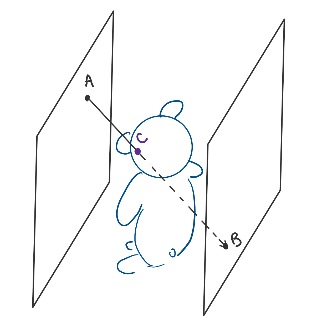
In theory, the particles can be generated according to any distribution, and modeling of their collision with the mesh can be arbitrarily complicated, as in a 56-page-long NASA report on “Abrasion by Aeolian Particles: Earth and Mars” (Greeley et. al. 1984). However, we chose a more simple model: the particle starting location is sampled from a uniform square on one side of the mesh, while its ending location is sampled from a uniform square on the opposing side of the mesh (Figure 3). We were able to achieve visually compelling results with this method, despite holding particle mass and velocity constant.
|
In order to determine the point of intersection between the particle and the mesh, we used a Bounding Volume Hierarchy, constructed with the Surface Area Heuristic introduced in class. However, since the mesh is constantly being updated due to the particle collisions, we need to make a slight modification. For each face and node in the BVH, we keep a pointer to its parent. Then, after the vertices of a face are updated, we check if the face’s new bounding box exceeds its parent node’s bounding box. If it does, we update the parent node’s bounding box, and check if the parent’s new bounding box exceeds its parent’s bounding box. We repeat this process as long as the current node’s bounding box exceeds its parent’s.
Once we have determined the collision point between the particle and the mesh, we displace the vertices of the collision face according to Equation 1. Simplifying the NASA report (Greeley et. al. 1984), there are two major mechanisms of erosion: chipping (first term of Equation 1) and fracturing/denting (second term of Eq. 1, Figure 4). In Eq. 1, the 0.5*m*v*v term is the kinetic energy of the particle, the a term is the barycentric coordinate of the point of intersection corresponding to the vertex in question, the sin(𝜽) and sin(2𝜽) terms involve the angle between the particle and the face normal, the 𝞓AREA term is a normalization term for the area of the triangle so that larger faces are not dented more deeply than smaller ones, and the HARDNESS terms are functions of space and provide texture.
|
|
Using a uniform hardness map, we were able to achieve the hailstorm and acid rain images pictured in the results section. However, in order to achieve more rock-like textures, it was necessary to add an anti-creasing measure (Figure 5). Without this measure, we found that we often generated sharp folds and creases, which are not common artifacts of weathering due to wind abrasion. To prevent these sharp creases, after indenting a face, we check if the angle between it and its neighboring faces is sharper than a threshold. If this is the case, we take the two shared vertices between the faces and move them in the direction of the average of the face’s normal vectors. If this smooths the crease, we continue the process until the angle threshold is reached. If not, we move the vertices in the opposite direction until the angle threshold is reached. We are able to do this since the two face’s normal vectors are guaranteed to either both point into or out of the mesh due to the half-edge winding direction being constant.
|
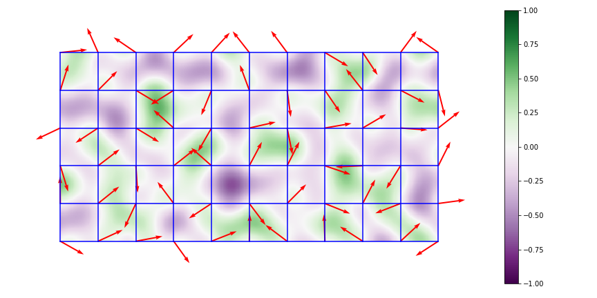
To achieve more interesting textures, we also constructed non-uniform hardness maps using multiscale Perlin noise. Perlin noise, introduced by Ken Perlin in 1983, is a smoothly spatially varying type of gradient noise which can be used to produce natural-looking textures at a given spatial scale (Figure 6). In the spirit of brevity, we will not describe the full algorithm used to generate Perlin noise here, but a description of the 2-D algorithm is given at https://en.wikipedia.org/wiki/Perlin_noise. To generate multi-scale Perlin noise, we simply sum Perlin noise at several octaves and normalize by the square root of the number of scales. After some experimentation, we settled on a conversion from the Perlin noise value to CHIP_HARDNESS and DENT_HARDNESS as in Equation 2. However, the two hardnesses were calculated using independent multi-scale Perlin noise maps. A visualization of the hardness map is shown in Figure 7.
|
|
|
Lastly, we added color texturing, again based on multi-scale Perlin noise. We found that choosing a grayscale value based on the Perlin noise value according to Equation 3 yielded a granite-like color texture map.

|
While doing this project, we ran into a few problems. As previously mentioned, we needed to implement anti-creasing to achieve wind abrasion-like textures. We also found the Greely paper and implemented chipping (in addition to denting) during our efforts to achieve more wind abrasion-like textures instead of a pock-marked landscape. Further, figuring out the formulae for converting from Perlin noise to the hardness maps and color texture took a lot of trial-and-error. Lastly, the most notable bug we encountered occured because we did not originally normalize the indentation by triangle area, so the small triangles stuck out more.
Overall, we were pleasantly surprised by the quality of results we were able to achieve with our project, given that we did not use a particle-based simulation, the novelty of the problem, and the limited amount of prior work for wind abrasion on meshes. We were very happy to see that a relatively straightforward extension of the project 2 and 3-1 codebases was able to achieve such striking results, showing that not all algorithms need be complex or computationally intensive.
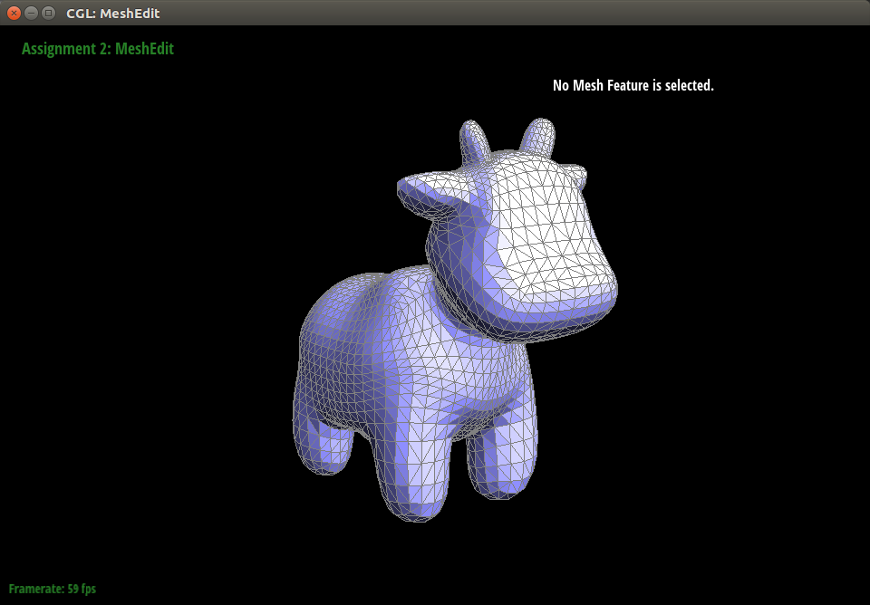
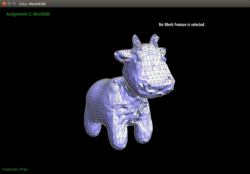
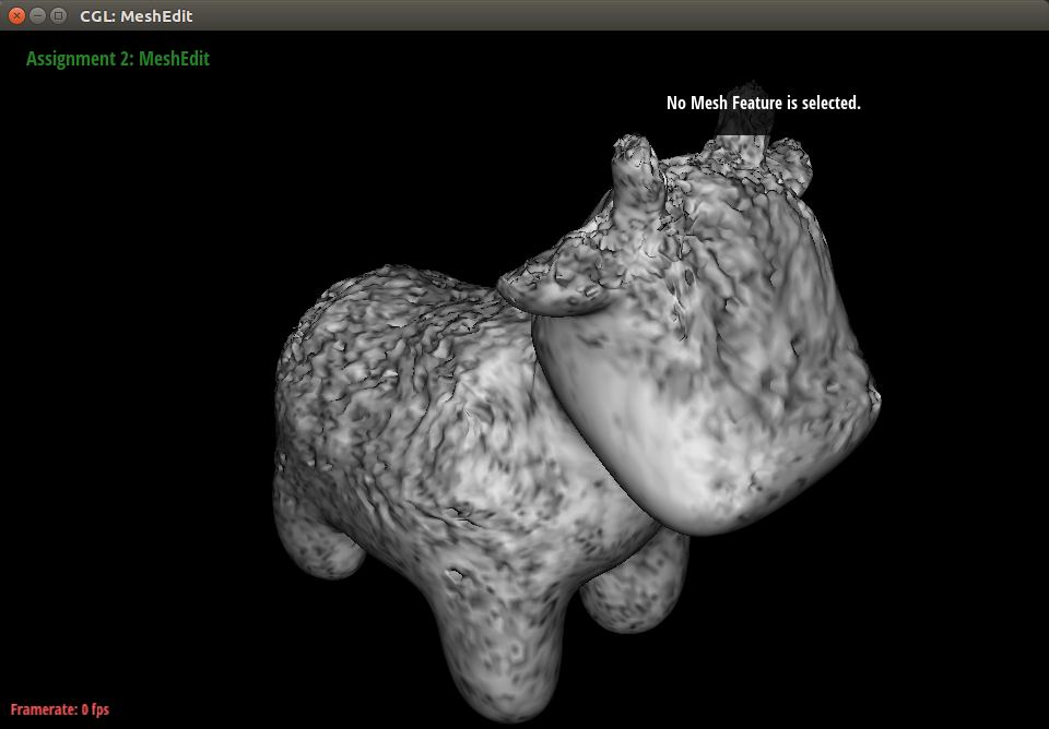
The simplest case we generated was to mimic a hailstorm. All particles move in the same direction. For example, you could subject a cow-mesh to particles coming from a head-on direction.
|
|
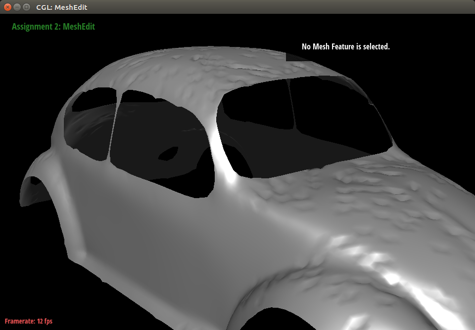
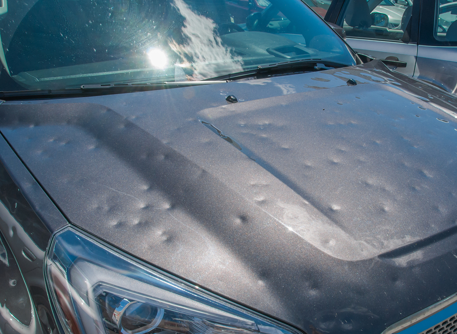
For a more relatable and useful example, we subjected the hood of a VW Beetle to particles that came from above. This left dents in the Beetle’s hood, quite similar to what can happen to a car left out in a severe hailstorm.
|
|
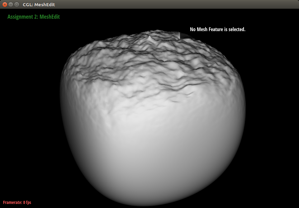
With minor modifications to the hailstorm case, we were able to generate surfaces that looked like they had been weathered by acid rain. The particles still come from the top, but they have more energy and therefore indent the mesh more deeply upon impact. This resulted in very jagged and rugged bumps and gouges similar to those left behind on statues exposed to acid rain. It is also interesting to note that this result looks very similar to mountain ranges, so this technique could also be applied to create landscapes.
|
|
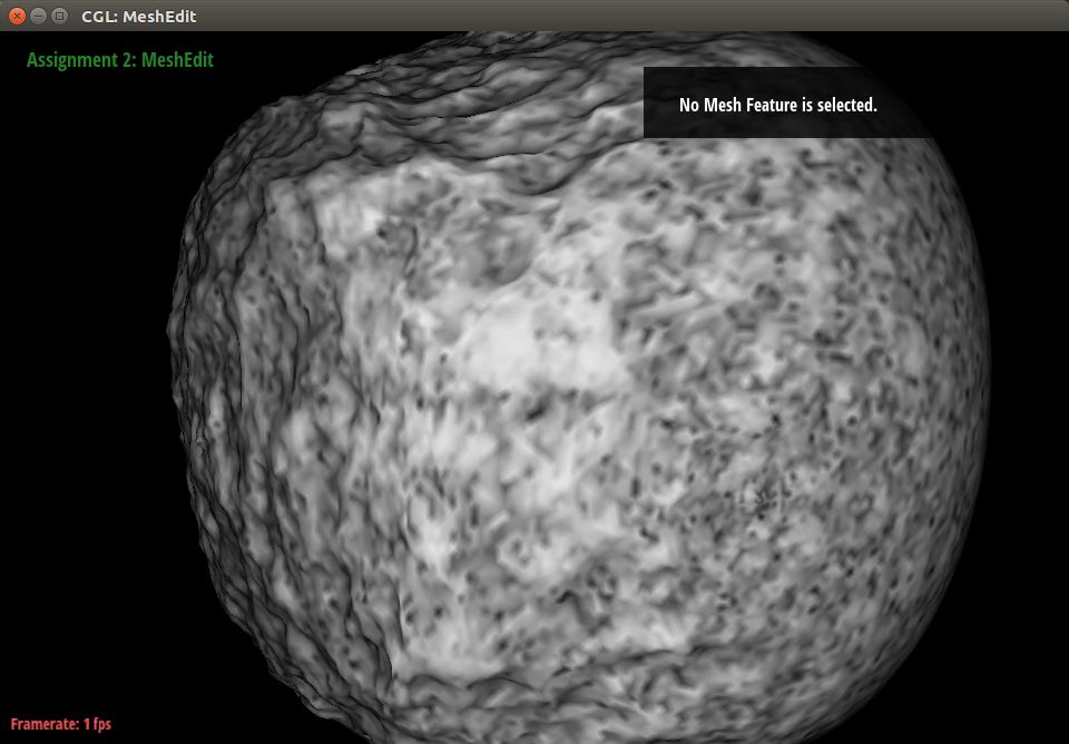
The sandblasted marble result looks much smoother and has shallower dents compared to the acid rain result. This gives a much more visually appealing appearance. We were able to achieve this look by implementing anti-creasing measures to prevent sharp edges and adding varying hardnesses along different points for more varied dents.
|
|
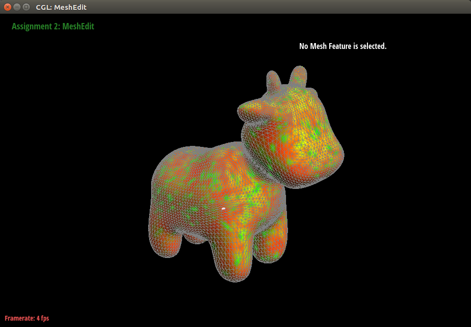
By adding a 2D texture to the sand-blasted marble result, we could also recreate something that looked similar to granite rock.
|
|

alvinz@berkeley.edu
Alvin was responsible for introducing the anti-creasing measure, generating the hardness map, and creating the granite texture.

seo.jysk@berkeley.edu
Stella was responsible for literature review and documentation for reports. She also helped organize the code architecture and made the website.

kangdoreene@berkeley.edu
Doreene was responsible for implementing the mesh-denting algorithm that created the Hailstorm and Acid Rain results. She also created all videos to document work.

Professional Dog
Moral support.

Professional Dog
Moral support.